Home Security with Systematic Design in NI LabVIEW and NI DAQ devices
- Overview
- Apparatus
- Design Purpose
- Sensor Evaluation
- Design Phase
- System Integration
- Conclusion
- Disclaimer
Overview
The main purpose of this project is to create a LabVIEW-based application for in-house security serving both hazardous and intruder threats. Three different kind of sensors will be implemented into one Virtual Instrument (VI) and cooperate with actual physical controllers and indicators.
That is, with advanced graphical programming approach, the workflow is optimized with proprietary products from National Instrument such as NI ELVIS Board and NI DAQ for data acquisition, simulation and design implementation. Namely, PIR Motion sensor HC-SR501, Temperature sensor LM35 and Gas sensor MQ-2 were selected to achieve the desired tasks.
This project was done as part of the Electronic Design Automation (EDA) Tool course which was conducted entirely in a sponsored laboratory by NI at RMIT University, School of Science and Technology, SGS Campus.
Apparatus
- NI LabVIEW Software
- NI DAQ
- NI ELVIS Board
- PIR Motion Sensor - HC-SR501
- Temperature Sensor - LM35
- Gas sensor - MQ-2
- Actuators: Fan, lighter, hand movement
Design Purpose
Home security is important because you never know when your home can be a target of burglary. Most home burglaries happen from 6 am to 6 pm when you are at work and your insurance company may cover some of the items stolen, but you can never replace priceless items.
Not only does home security alert the proper authorities in the event of a break, but nowadays most home security companies offer interactive home security features to alert you almost immediately when your alarm system is going off.
This project aims to provide such system with fully marked workflow from behind-the-screen execution to graphical user interface at your conveniences.
Sensor Evaluation
For instance, Temperature sensor selection was classified based on several characteristics
-
Requirement: Create a system that monitoring the indoor temperature 24/7, suitable reaction when detects abnormal increase. The quality of the system is the main focus with many functions executed concurrently gives the only outcome which is detect and prevent any potential temperature-related incident such as fire, explosion, etc. Moreover, the system will be user-friendly and well-organized and the transparency in data storing and displaying are also strongly emphasized.
- Control aspect
- A Boolean True/False (i.e. Master Button) to set everything up gives the user the ultimate control of the whole function.
- A Numeric control (i.e. Upper/Lower Limit) provides the flexibility for the user to change the range of temperature based on the location or season.
- Monitor aspect
- A thermometer indicates the temperature at the moment precisely and quickly.
- A histogram shows the temperature oscillation simultaneously and store the collected data for later uses.
- Status aspect
- A string indicator (i.e. Temperature Status) displayed in English is common and simple to understand with the majority of user.
- A pop-up message warning user when putting invalid input into the limit(s) also included.
Similarly, other sensors were also evaluated and selected as the most suitable components serving this multi-purpose of a system.
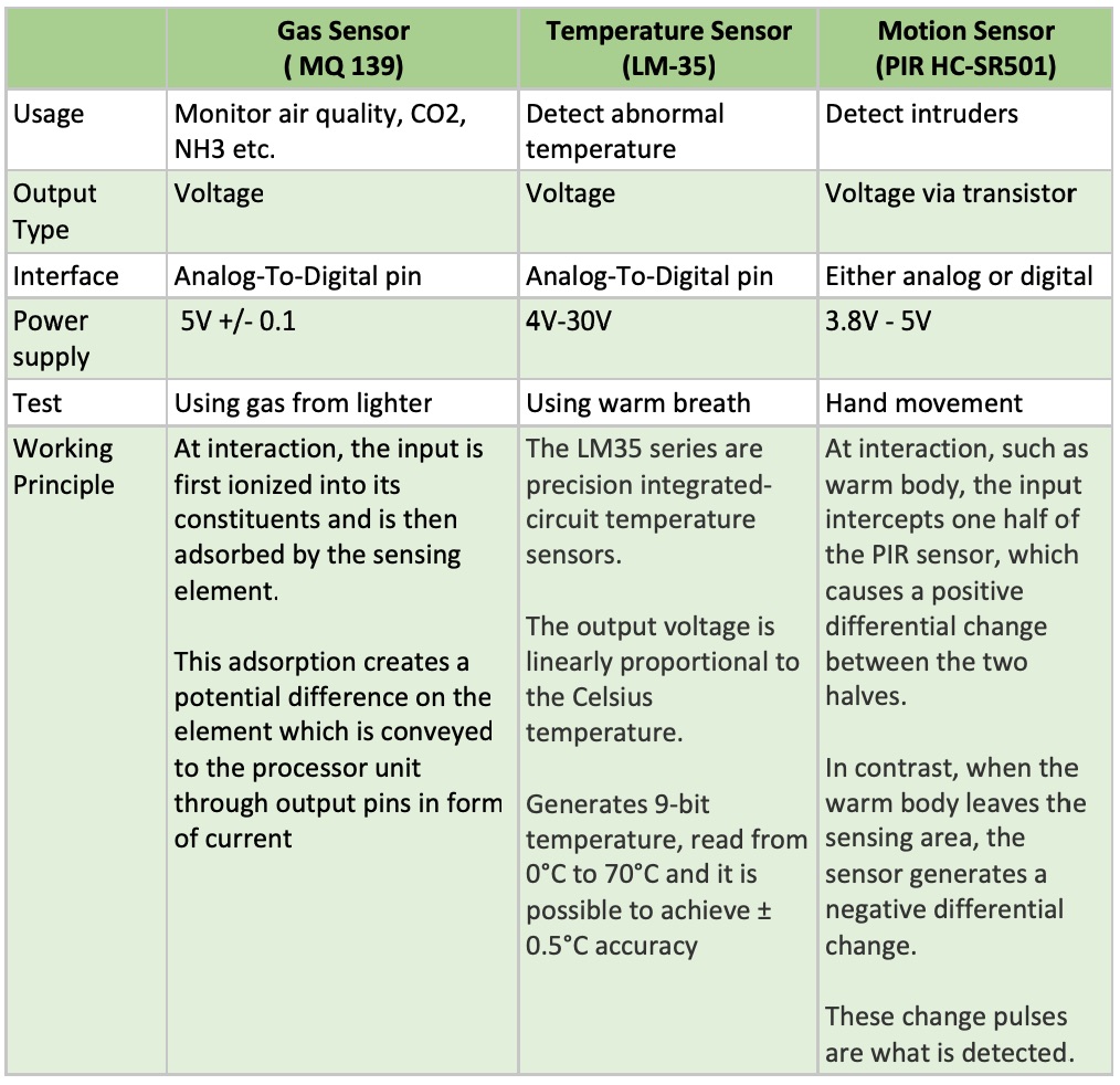 Sensor analysis and parameters. All considered from both hardware and software perspective as well as their functionality and test scenarios.
Design Phase
The DE of NI LABView provides toolbox from two windows: Front Panel and Block Diagram and reflect each other states. Specifically, the Front Panel includes controls and indicators, whereas the Block Diagram includes wires, icons, functions, possibly subVIs, and other LabVIEW objects.
User Interface
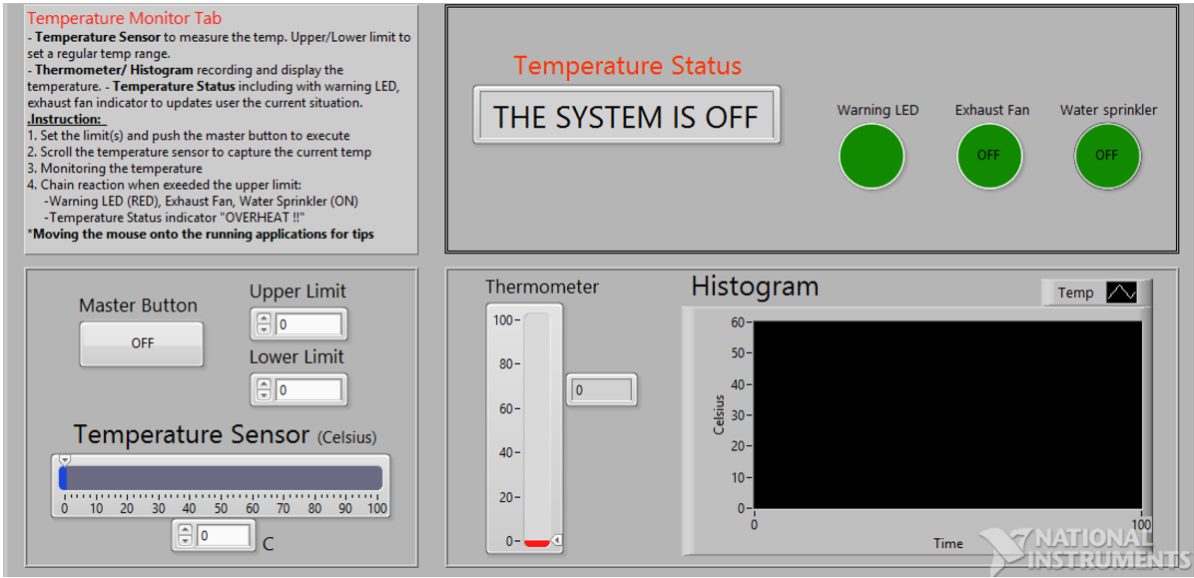
In case of the Temperature Sensor, the sensor with a button (ON/OFF), 2 numeric controls (limit), a status indicator, 3 indicators (LEDs), a thermometer, a histogram and a horizontal slide bar (temperature sensor). The temperature sensor activated automatically using Master Button in ‘Always On’ mode.
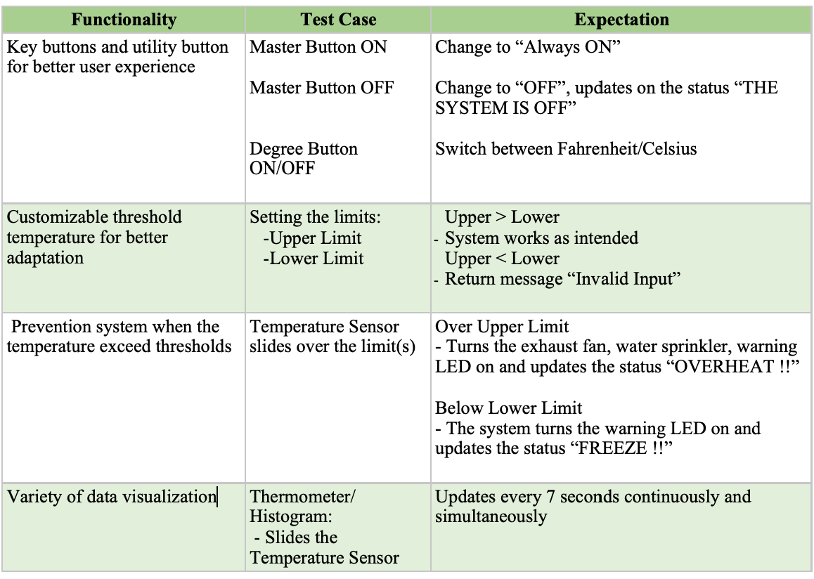
Master Button is in OFF state, all the indicators turned off and the status changes to “THE SYSTEM IS OFF” as a reminder to the user.
On the Front Panel, there are 3 main sections: Control, Monitor, Status and an information tab (Temperature Monitor Tab).
Control:
- Master Button: A launch button with two modes: Always On/OFF
- Upper/Lower Limit: setting a specific range of temperature that suitable with the house geographical location. Furthermore, the unit of temperature measured is Celsius (ºC).
- Temperature Sensor: captures the current temperature indoor by scrolling left or right (0-100). A numeric indicator also included.
Monitor:
- Thermometer: measure the temperature simultaneously, also in Celsius.
- Histogram: Display the oscillation of the temperature and storing the data.
Status:
-
Temperature Status: Display the current situation (“FREEZE !!” when the temperature dropped below the Lower Limit, “OVERHEAT !!” when the temperature risen over the Upper Limit)
-
LED(s): Warning LED, Exhaust Fan, Water Sprinkler indicators will be triggered when the temperature exceeded limit and turns off after the situation controlled automatically.
Functionality
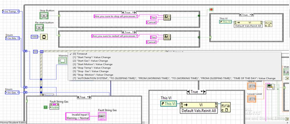
On the other hand, the block diagram represents the mechanism of the temperature sensor. Within the While Loop for the whole program, the case structure used to run many functions based on the Boolean Master button.
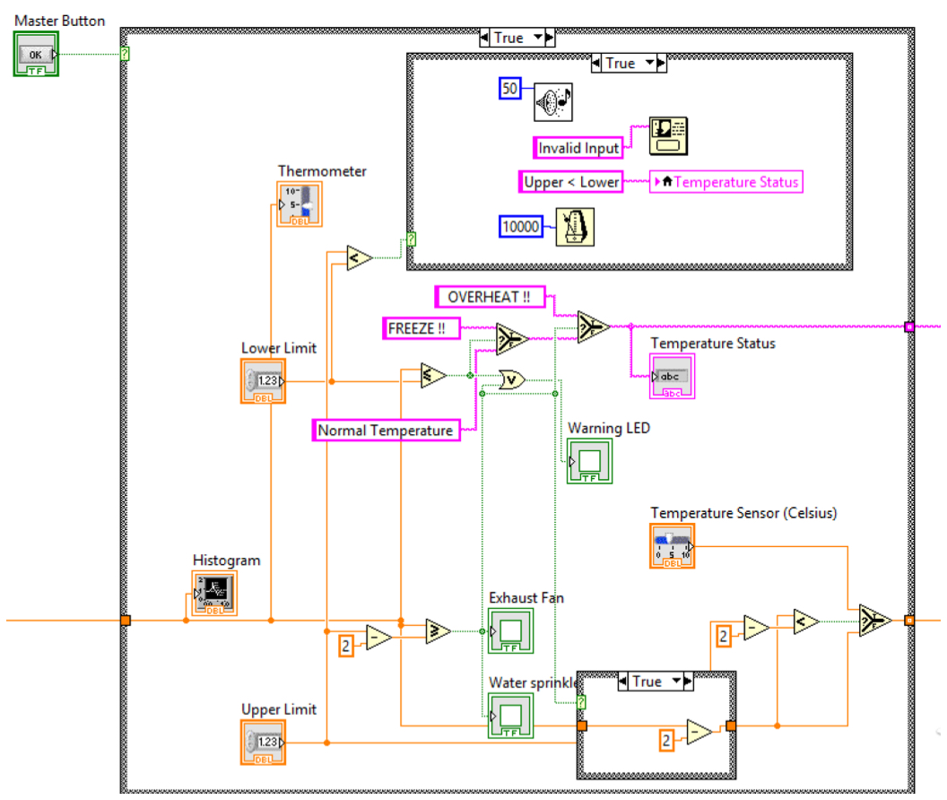 Conceptualize the process of such system with a decrement of 2 degree Celsius when the actuators are activated.
Specifically, a case structure is used to demonstrate the outcome when the exhausted fan was activated, i.e. the temperature over the upper limit. The current temperature dropped by 2 degree every cycle as indicated by the Thermometer and will only stop when the temperature measured dropped below the upper limit.
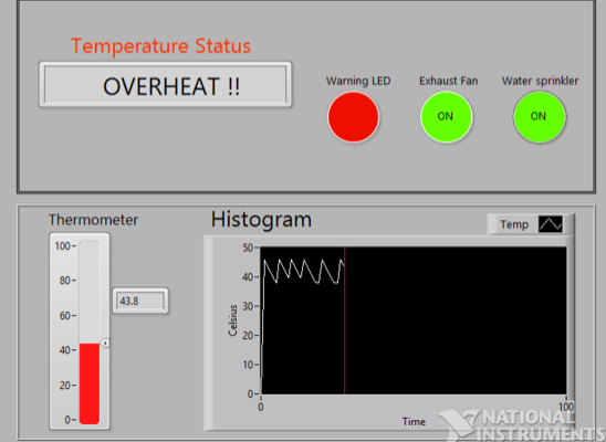 Exceed temperature of a 40 degree limit automatically activates all the precaution measurement
When the temperature back in range (below upper limit), by using the Shift Register, a new value will be taken by the temperature sensor as originally. The precaution system (Exhaust fan, LED, water sprinkler) is then turned off accordingly.
Another application using case structure is the feedback when the input for two limits is invalid (i.e. Upper Limit < Lower Limit), then the case structure will return a message Invalid Input and update the temperature status Upper < Lower to inform user the current state. A ten-second delay for user to change the values also included.
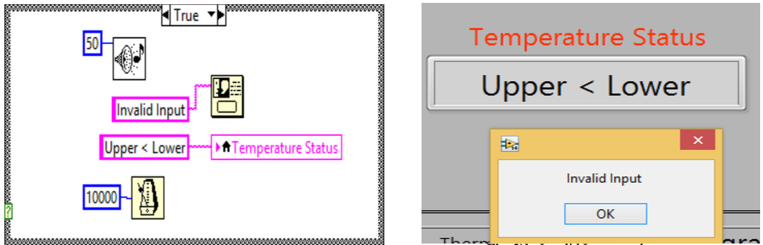 Invalid Input feature implementation and the system in action
System Integration
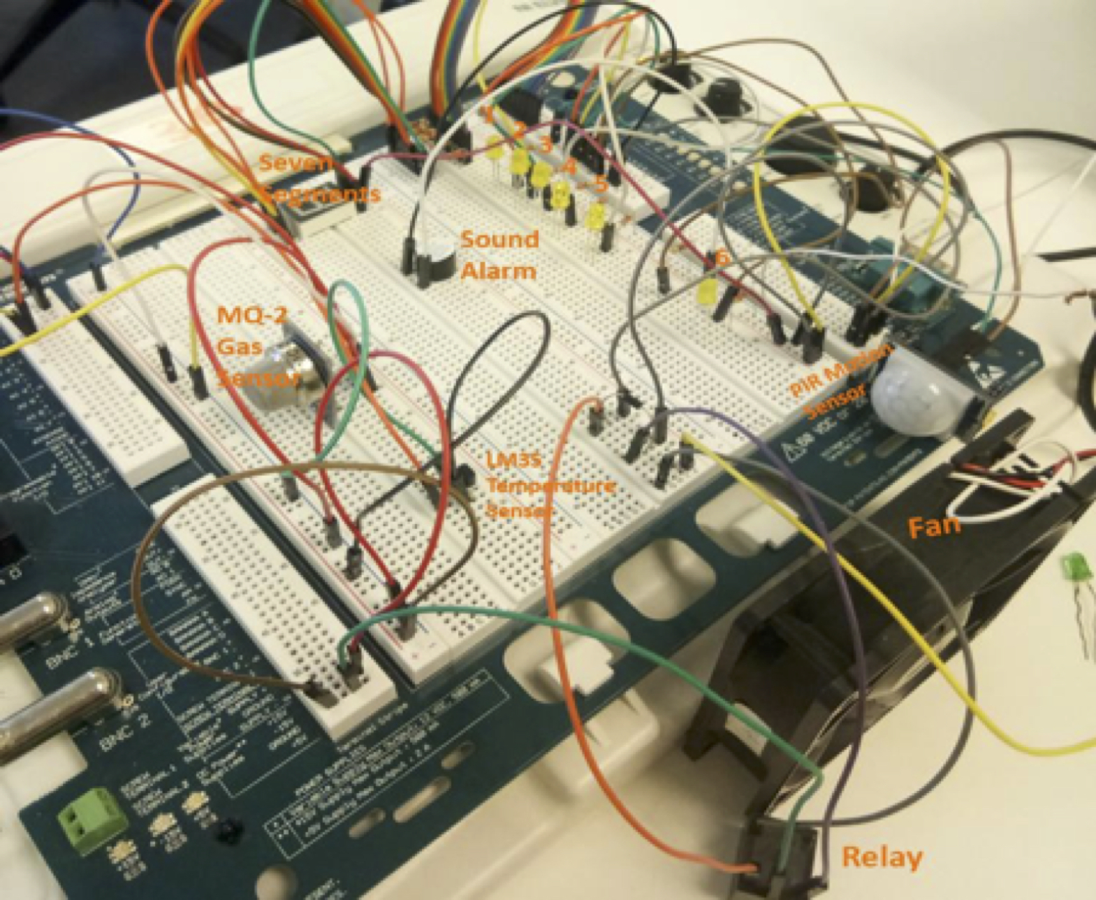 Physical implementation of the whole system on NI ELVIS Board
Data Acquisition (DAQ)
With the change from a “prototype” control to actual Data Acquisition devices, the precision in collecting data and the VI workflows are expected to be even more meticulous. The DAQ VI collects data from the sensor which wired into a processing hardware (ELVIS Board), then digitized to work on software (LabVIEW).
 Physical implementation of the whole system on NI ELVIS Board
Data Conversion & Export
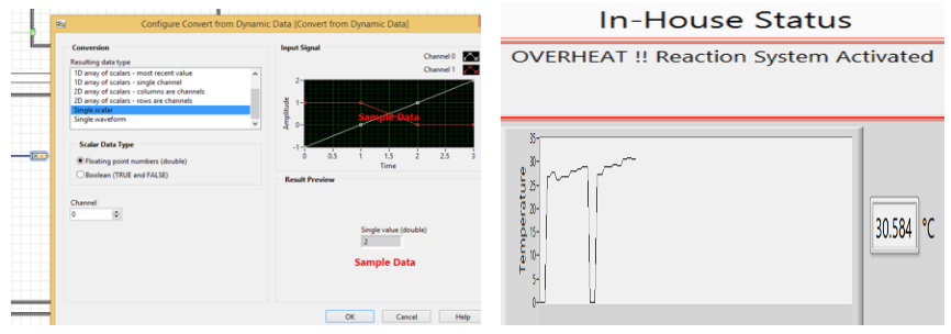
A must-have pre-process is converting data, where the temperature readings displayed in form of signal, into numeric using LabVIEW function Convert from Dynamic Data. With the converted numeric data, the Measure Temp subVI will do calculation to determine whether the current temperature is abnormal.
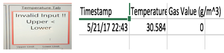 Actual response of the system and data export to comma separate value (.csv) format
Following by, displaying the current temperature on both graphical and numeric. An export data option also included for the user to collect the temperature readings.
Finite State Machine Design
The state machine with designated cases make sure the three sensors can measure independently without troubling each other while keeping synchronization. Also, the event-driven structure keeps the VI memory-friendly since it only starts when an event occur, thus minimize CPU usage.
 Invalid Input feature implementation and the system in action
Replacing for the hard-wired way to restart the VI previously, the invoke node with a reinitialize all values to default method connecting a VI reference to restart the whole VI and prevents any potential error.
Troubleshooting
 Test case for Temperature Sensor with 5V DC Fan and integration with user interface
Two DAQ assistants ( analog input ) can’t be put inside a same loop
Add more channel in 1 DAQ assistant
The sub-system collapsing when using more than 1 event-driven structure in 1 while loop
Using only 1 event-driven structure for three sub-system combining with shift register and enum function to make a state machine
The status indicator still updates even when the input is syntactically illogical. Specifically, Upper Limit smaller or equal to Lower Limit OR Warning Rate smaller or equal to Normal Rate
Debug the subVI and synchronize the status strings
Conclusion
The system meets requirements of a complete in-house security system with gas sensor to detect leaked gas; temperature sensor to measure the temperature and motion sensor to detect unintended movement passing through the sensor. All 3 parts use basic and advance functions to improve the system from prototype to using actual DAQ devices.
Overall, the complete of this project serves various purpose, resolves different algorithms from the basic programming to the advance one and function from the computer using LABView and then actually connect to the actual controllers and actuators such as ELVIS board , sensors and many other components to carry out the VIs created in real life and work with everything hands on using the software.
Disclaimer
This article offers knowledge and personal opinion based on the author’s point of view which perceived at the time of writing this article.
It is intended to serve “as-is” without any guarantee to work, proceed with caution. Your inputs and feedbacks are welcome as always.